Volumetric Fog: Frustum-Aligned Compute-Based Atmospheric Scattering


The Volumetric Fog system was implemented following the main architecture presented by Bart Wronski in “Volumetric Fog: Unified Compute Shader Based Solution to Atmospheric Scattering” at SIGGRAPH 2014. The core idea is to represent the participating medium inside a camera-aligned 3D volume, evaluate density and lighting per volumetric cell, integrate scattering along the view direction, and finally composite the accumulated result with the rendered scene. Wronski describes this as a sequence of volumetric lighting/shadowing, medium-density estimation, a 2D raymarch through the volume, and final screen application.
The physical model is based on the interaction of light with a participating medium. Light travelling through fog can be scattered into the camera, scattered away from it, or absorbed. In particular, the implementation uses Beer-Lambert transmittance to model the exponential loss of light with distance through the medium.
1. Scene-level Volumetric Fog settings
A new VolumetricFogSettings configuration was added to the Scene. It exposes the main artistic and physical parameters of the effect, including density, scattering coefficient, extinction coefficient, anisotropy and maximum fog distance. The settings are serialized with the Scene, restored correctly when entering and leaving Play Mode, and exposed through the Scene Configuration panel.
This separates fog authoring from individual lights and makes Volumetric Fog a global scene property. Directional lights remain independent and are consumed later as an input to the volumetric-lighting stage.

2. 3D volumetric texture infrastructure
Wronski's solution stores intermediate atmospheric information in 3D textures, allowing compute shaders to process the participating medium volumetrically.
The engine's texture system was extended with proper Texture3D UAV support, and three 160 × 90 × 64 floating-point volumes were introduced:
VolumetricFog_Medium
VolumetricFog_Lighting
VolumetricFog_Integrated
The selected resolution is directly inspired by one of the layouts described by Wronski. A relatively low-resolution volume keeps the lighting cost largely independent from the final screen resolution.

3. Frustum-aligned froxel grid
Instead of representing the fog using a world-aligned volume, the 3D texture is mapped directly to the camera frustum. XY coordinates correspond to normalized screen coordinates, while Z represents distance from the camera.
Wronski specifically recommends this layout and uses an exponential depth distribution, concentrating more slices near the camera where precision is most important.
The implementation therefore uses:
160 × 90 × 64 froxels
with exponentially distributed depth slices between the camera near plane and the artist-defined Max Distance.
The exact exponential mapping function used by the engine is an implementation choice; Wronski defines the principle of near-camera-concentrated exponential distribution but not a mandatory formula.

4. Participating-medium injection
The first real compute stage fills VolumetricFog_Medium.
For every froxel, the shader calculates effective scattering and extinction coefficients:
scattering = density × scattering coefficient
extinction = density × extinction coefficient
RGB stores the effective scattering coefficient and alpha stores extinction.
This stage corresponds to Wronski's participating-media density estimation. His implementation combined density and lighting for bandwidth reasons, but explicitly states that both calculations can be separated and fully decoupled. Separating them in this engine makes the data flow clearer and leaves room for future density sources such as local fog volumes.

5. Directional volumetric lighting
A second 3D compute pass evaluates directional-light in-scattering for every froxel. Each cell reconstructs its world-space position from the camera-aligned grid.
The directional response uses the Henyey-Greenstein phase function. Wronski identifies Henyey-Greenstein as a common and efficient approximation for Mie-like anisotropic scattering and notes that its anisotropy factor can be changed at runtime.
Wronski's Assassin's Creed IV implementation used an art-directed phase response, but the presentation explicitly notes that a physical phase function can be substituted in this stage. This implementation therefore uses Henyey-Greenstein to give the Anisotropy setting a physically meaningful directional response.
[Image: Henyey-Greenstein response for negative, zero and positive anisotropy]
6. Cascaded-shadow integration
Directional shadows were then added to the volumetric-lighting calculation.
The existing Cascaded Shadow Map is sampled directly from the compute shader for every froxel. The reconstructed world position is transformed into the relevant light cascade and the same shadow bias, strength and PCF configuration used by regular scene lighting is applied to the volumetric contribution.
This creates volumetric shadows and allows geometry to block light travelling through the fog.
Wronski used downsampled and filtered Exponential Shadow Maps for the main volumetric light. Our implementation intentionally differs here: the engine's existing CSM is reused directly to avoid introducing a second shadow representation. The CSM resource state was therefore extended to:
PIXEL_SHADER_RESOURCE | NON_PIXEL_SHADER_RESOURCE
allowing Deferred Lighting to sample it from a pixel shader while Volumetric Fog simultaneously consumes it from compute.

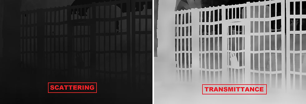
7. Scattering and transmittance integration
Once Medium and Lighting are available, a third compute shader performs the actual volumetric integration.
Unlike the previous 3D dispatches, this stage uses a 2D compute dispatch. Each thread corresponds to one XY column of the froxel grid and sequentially walks through all 64 Z slices.
This directly follows Wronski's integration strategy, where a 2D compute group marches through the 3D volume while accumulating in-scattered lighting and extinction.
For each segment, Beer-Lambert is evaluated:
Tsegment = exp(-extinction × segmentLength)
and both scattering and transmittance are accumulated from the camera toward increasing depth.
VolumetricFog_Integrated therefore contains:
RGB = accumulated in-scattered radiance
A = accumulated transmittance
at every depth slice.
This allows any later pixel to retrieve the result already integrated from the camera up to its own depth.
8. HDR scene composition
The integrated volume is finally applied through a fullscreen pixel pass.
The full-resolution scene depth is used to determine how far along the volumetric grid each pixel lies, after which the corresponding accumulated scattering and transmittance are sampled from the 3D texture.
This follows another important property of Wronski's approach: although volumetric calculations are performed at low resolution, full-resolution fragments use their own depth when sampling the 3D volume, allowing 3D interpolation without the severe depth-discontinuity problems associated with conventional low-resolution 2D fog buffers.
The final HDR composition is:
FinalColor = SceneHDR × Transmittance + AccumulatedScattering
The fog is applied after the Skybox and before Particles, Trails and Post Processing, so all opaque HDR scene lighting and the sky receive volumetric attenuation before tone mapping.

9. Volumetric debug views
Several debug modes were added to inspect each stage independently:
Medium / Extinction Slice
Lighting Slice
Lighting without Shadows
Accumulated Scattering
Transmittance
Final
These views are particularly useful because Volumetric Fog consists of several dependent GPU stages. A problem can therefore be isolated immediately: an incorrect Medium view points toward density generation, incorrect Lighting toward the directional/phase/shadow stage, and incorrect Transmittance toward integration.
PIX GPU captures were also used to validate the compute dispatches, SRV/UAV bindings and D3D12 resource transitions between Medium, Lighting, Integration and the CSM.
10. Optional animated fog density
As a final extension, the participating medium can optionally be animated.
Wronski describes using one octave of Perlin noise animated by wind for density estimation, noting that additional octaves produced only a subtle improvement for their added cost.
The same concept was introduced into VolumetricFogInjectMediumCS. When animation is enabled, each froxel reconstructs its world-space position and evaluates a low-frequency Perlin field displaced over time by a configurable wind vector.
Designers can control:
Animate Density
Noise Scale
Noise Strength
Wind Direction
Wind Speed
Because the noise is evaluated in world space, the fog remains spatially stable when the camera moves; only the simulated wind transports the density field.
Animation is completely optional. With Animate Density disabled—or Noise Strength set to zero—the system returns to the original homogeneous medium.
Final result
The completed system follows the main structure of Wronski's SIGGRAPH 2014 technique while adapting it to the existing DirectX 12 Game Engine:
Frustum-aligned 3D froxel grid
↓
Medium Injection
↓
Directional Lighting + HG + CSM
↓
2D depth integration
↓
Accumulated Scattering + Transmittance
↓
Full-resolution depth lookup
↓
HDR Composition
The most significant implementation difference from Wronski's Assassin's Creed IV solution is the shadowing path: the existing Cascaded Shadow Map is sampled directly instead of generating the filtered Exponential Shadow Map representation used in the original implementation. Density and lighting are also stored in separate volumes, a separation explicitly supported by Wronski's architecture.
The resulting system provides physically motivated extinction, anisotropic directional scattering, volumetric shadows, depth-aware HDR composition, debugging tools and optional animated density while preserving a fixed low-resolution volumetric workload. It also establishes a structure that can later be extended with local density volumes, additional volumetric lights or more advanced atmospheric effects without replacing the core pipeline.


Comments